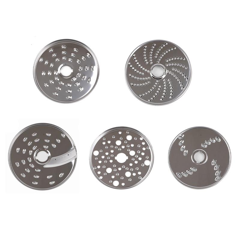
Stainless steel food processor discs are developed through a sequence of design review, material selection, forming and inspection steps. The exact route depends on the disc geometry, cutting pattern, mounting interface and approved project requirements. A reliable OEM supplier should explain the route in terms of the part rather than promise a generic process for every disc.
This article outlines the review stages used for a custom food processor disc and shows how the work connects with broader metal stamping and forming capabilities. For a complete appliance program, the related food processor parts page covers blades, grater components and other parts.
1. Material and Drawing Review
The project begins with the customer drawing, sample or current component. Engineering reviews the requested material, thickness, disc outline, center opening, mounting holes, cutting pattern and surface requirements. For selected disc programs, 420/430 stainless steel is referenced on the product page. The approved project information remains the controlling source for final material selection.
Why the Reference Matters
Two discs can have the same outside diameter but different appliance interfaces. The center opening, hub relationship, hole position and edge direction all affect assembly. A sample also helps identify whether the required function is slicing, shredding, grating, julienne, French fry cutting or dicing.
2. Blanking and Stamping
After the design is reviewed, the flat disc form is produced through a suitable stamping and blanking route. The tooling is developed around the approved geometry. Blanking defines the outside form, while subsequent operations may create openings, holes or formed features.
Stamping is not only a volume operation. For an OEM buyer, it also provides a controlled way to repeat the approved outline and feature positions once the tooling and process are confirmed. Trial samples allow the customer and supplier to review the actual part before regular production.
3. Cutting Pattern Forming
The cutting pattern is the functional center of the disc. Slicing edges, shredding openings, grating teeth, julienne slots and other patterns need to be formed in the correct orientation. The pattern must work with the appliance feed path and maintain the intended clearance around the disc.
Pattern Review Before Production
Pattern names alone are not sufficient for manufacturing. Fine shredding and coarse shredding, for example, imply different opening arrangements. The approved drawing or sample should define the practical geometry. Where the project is a replacement disc, the original component helps confirm the mounting interface and cutting direction.
4. Blade and Edge Processing
After the main pattern is formed, the cutting edges are reviewed for shape, direction and condition. Edge processing may be part of the stamping/forming route or a secondary operation depending on the approved component. The process should be selected to preserve the required geometry without adding unsupported claims about a specific machine or tolerance.
5. Surface Finishing and Assembly Review
Surface finishing is confirmed against the customer’s drawing and application. The supplier also reviews whether the disc is a standalone component or part of an assembly. Center interfaces, mounting holes and contact surfaces should be checked before the part is approved for the appliance program.
6. Inspection Against the Approved Design
Inspection compares the produced disc with the approved drawing, sample or agreed project requirements. Review points may include outline, hole position, pattern orientation, edge condition, surface appearance and assembly fit. The inspection plan should reflect the features that matter for the customer’s appliance rather than rely on a generic checklist.
What to Include in an RFQ
Send the part drawing or sample, material preference, required function, target appliance interface, annual or project context if available, surface expectations and any existing inspection criteria. Clear input helps the supplier plan tooling and identify questions before quotation.
Conclusion
Manufacturing a stainless steel food processor disc is a connected process: review the design, select the material, form the disc, create the cutting pattern, process the edge, inspect the result and confirm assembly. Shengyue evaluates these requirements from customer drawings or samples for OEM projects.
How Engineering Review Reduces Project Risk
Early engineering review is valuable because food processor discs combine thin sheet geometry with a functional cutting edge. Small differences in the center interface or pattern direction can affect assembly. Reviewing the sample, drawing and appliance context together helps the supplier ask the right questions before tooling is approved.
Buyers can support the review by identifying which dimensions are critical, which surfaces are visible, how the disc is cleaned or handled, and whether the component is a new design or a replacement. This information does not need to become a long specification document; a clear drawing with notes and one representative sample is often a practical starting point.
Prototype Feedback and Production Release
A prototype or trial sample creates a useful checkpoint. The buyer can check the disc in the appliance, confirm the cutting result and review the visual finish. Any adjustment should be recorded against the drawing before production release. This keeps the approved design, tooling route and inspection focus aligned.
Documentation That Helps the Supplier
A good manufacturing package normally includes a current drawing, a sample or clear reference photographs, the intended appliance interface and any known material requirement. Mark critical features such as the center opening, mounting holes, cutting edge direction and visible surfaces. If the disc is part of an assembly, include the mating component or interface drawing where possible.
Buyers should also identify whether the part is a new design, a replacement, a tooling transfer or a change to an existing component. That context affects how the supplier plans review and sampling. It also helps separate a design feasibility question from a production quotation.
Managing Changes
Changes should be recorded after sample review. A revised hole position, cutting pattern or thickness can affect tooling and inspection, so the drawing revision should identify what changed. Keeping a single approved version reduces confusion between engineering samples and production parts.