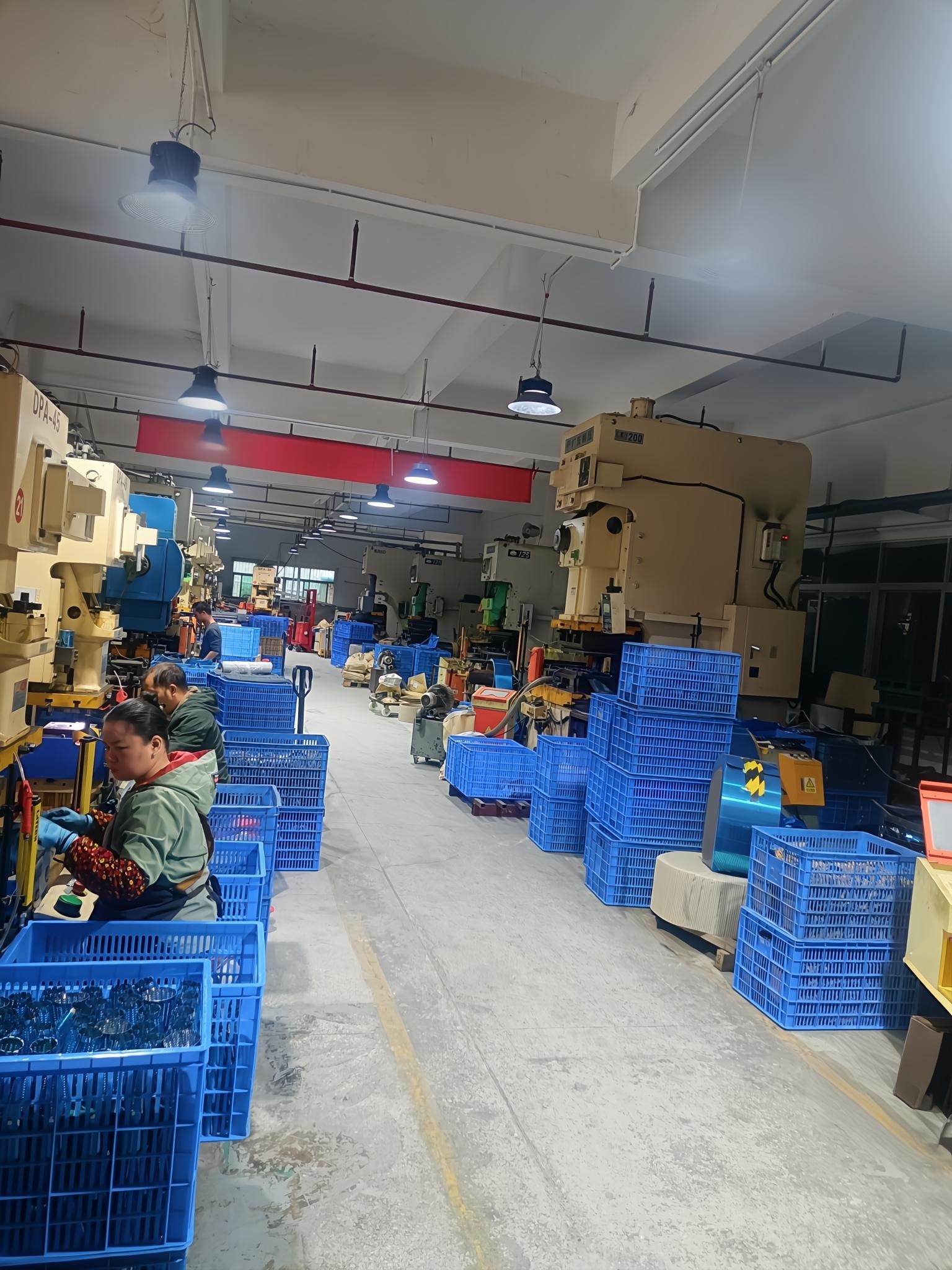
Why do stamped metal parts develop burrs, cracks, wrinkles or dimensional variation? Defects can arise from the interaction of material properties, tooling condition, press setup, lubrication and part geometry. A useful corrective action starts with identifying the actual defect and measuring it against the drawing—not simply polishing away visible evidence.
This guide is written for OEM buyers, product engineers and sourcing teams evaluating custom metal stamping suppliers. It explains common defect mechanisms, realistic prevention methods and the inspection information to include in a manufacturing RFQ.
Common Metal Stamping Defects at a Glance
| Defect | Typical contributors | What to verify |
|---|---|---|
| Burrs or sharp edges | Tool clearance, worn cutting edges, alignment or material variation | Burr location, height, direction and edge requirement |
| Cracks or splits | Excessive forming strain, small radii, unfavorable grain direction or unsuitable material | Crack location, bend radius, material temper and formability |
| Wrinkles | Insufficient material restraint, blank-holder setting or draw geometry | Wrinkle location, draw depth and holding force |
| Dimensional variation | Springback, tool wear, press variation or inconsistent stock | Critical dimensions, datum scheme and measurement method |
| Scratches or dents | Handling, debris, tooling contact or inadequate protection | Cosmetic zones, handling process and surface-finish criteria |
| Distortion or warping | Residual stress, uneven forming or downstream processing | Flatness, functional fit and process sequence |
These are possible causes, not a universal diagnosis. Root-cause confirmation requires examining actual parts, tooling, material records and process data.
1. Stamping Burrs: Causes and Control
A burr is a raised or torn edge left during shearing, piercing or blanking. Its severity can change with cutting clearance, punch and die condition, alignment, stock thickness and material strength. Excessive burrs may interfere with assembly, handling, coating or adjacent components.
Practical burr-control measures
- Specify the edge: define allowable burr height and where the requirement applies, using an agreed inspection method.
- Review cutting clearance: select and validate clearance for the actual stock and tool geometry; there is no single correct percentage for every material.
- Maintain tooling: inspect cutting edges, wear and alignment before defects become widespread.
- Control material variation: verify thickness, grade and relevant mechanical properties.
- Plan finishing: deburring, tumbling or brushing may be appropriate, but should not substitute for correcting an unstable cutting process.
For sharp-edged appliance components, clarify whether the edge is functional, hidden within an assembly or user-accessible. Those conditions may require different acceptance criteria.
2. Cracks and Splits During Forming
Cracking can occur when local strain exceeds the material's available formability. Tight bends, unfavorable hole-to-bend distances, insufficient corner radii and inconsistent material properties can contribute. Before changing a die, review the drawing, grain direction, material temper and forming sequence.
For stainless steel parts, a nominal grade alone does not define formability. Thickness, condition and the supplier's material specification also matter. See our stainless steel grades guide for application-level comparisons.
3. Wrinkling and Surface Damage
Wrinkles are more common in certain drawing operations when material flow is not adequately controlled. Adjustments may involve blank geometry, tooling radii, lubrication and blank-holder conditions. Scratches and dents, by contrast, may originate after forming from transfer, stacking or packaging.
If the component has a visible surface, provide a marked drawing showing cosmetic zones, acceptable marks and inspection lighting or viewing conditions. A vague instruction such as “no scratches” can lead to inconsistent supplier judgments.
4. Dimensional Accuracy, Springback and Tool Wear
After forming, elastic recovery can cause springback. Hole positions, bends, flatness and assembled fit may vary with tool condition and stock properties. A practical control plan distinguishes critical-to-function dimensions from noncritical features.
Request a documented first-article inspection for critical dimensions and agree on sampling frequency for production. For more on production readiness, see prototype-to-mass-production approval and stamping tooling development.
5. How OEM Buyers Should Specify Quality Requirements
| RFQ input | Why it matters |
|---|---|
| 2D drawing and 3D model | Defines geometry, datums, tolerances and assembly interfaces |
| Material grade, temper and thickness | Supports tool design and consistent forming behavior |
| Critical-to-quality features | Directs inspection effort to functional risks |
| Burr and edge-break requirements | Prevents disagreement over acceptable cut edges |
| Surface finish and cosmetic zones | Clarifies scratch, dent and coating acceptance |
| Annual volume and lot size | Helps select suitable tooling and inspection plans |
| Inspection report and traceability needs | Aligns supplier documentation with buyer expectations |
Use the custom metal parts RFQ guide when preparing your first supplier inquiry. The quality page explains our quality-focused manufacturing approach.
6. A Practical Inspection and Corrective-Action Workflow
- Contain: identify affected lots and separate suspect parts.
- Measure: record the defect location, frequency and magnitude against the agreed specification.
- Investigate: check tooling, material, machine setup, handling and recent process changes.
- Validate: test the proposed correction on samples before resuming normal production.
- Monitor: define ongoing checks and retain records for recurring issues.
Inspection does not make an unstable process capable. The objective is to reduce the causes of variation and verify that the process remains controlled.
Frequently Asked Questions
Can burrs be completely eliminated?
Many stamping processes produce some degree of edge deformation. The practical objective is to meet a clearly defined burr or edge-condition specification consistently, using suitable tooling and finishing where needed.
Is deburring always necessary?
No. It depends on the as-stamped edge, assembly function, handling risks and customer requirements. Specify acceptance criteria before choosing a finishing process.
What causes a stamped part to be out of tolerance?
Possible contributors include springback, tooling wear, stock variation, press setup and measurement differences. Inspect the actual feature and process before deciding on corrective action.
What should I send to a stamping supplier for a quality-focused quotation?
Send drawings, material and thickness, volume forecasts, critical dimensions, burr limits, finish requirements and inspection documentation needs. Include photos or samples of unacceptable defects when available.
Request an OEM Stamping Review
SHENGYUE manufactures custom stamped metal components and related formed parts. Share your drawing, material specification and defect or tolerance concerns so our team can review manufacturing feasibility and quotation requirements. Explore our product categories and manufacturing capabilities.